How Do You Guarantee a First-Time-Right Street Light Installation?
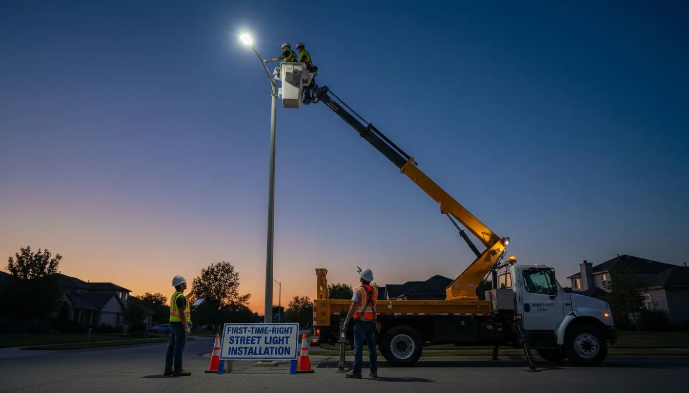
Callbacks on street light installs are costly and frustrating. They destroy your project's profitability and damage your reputation. A solid Standard Operating Procedure (SOP) is the only way to get it right the first time.
To guarantee a first-time-right installation, you must follow a strict SOP covering four key areas. This includes using calibrated torque wrenches1 for all fasteners, following exact wiring codes, precisely aiming fixtures to match the photometric plan, and preparing a complete, photo-documented acceptance packet for sign-off.

Over my 13 years in the LED lighting business, I've seen it all. I've seen entire projects delayed and profits erased by the smallest mistakes—a loose wire, a misaimed fixture, or a bolt tightened by "feel." These aren't just technical errors; they are business failures. The contractors who succeed, the ones like Somchai Wong in Thailand who manage massive commercial developments, don't leave these details to chance. They rely on process. They know that a successful project isn't finished when the lights turn on; it's finished when the final payment is in the bank and there are no callbacks. This guide is the SOP I've developed with my partners to ensure every installation is a success. It's about protecting your bottom line and building a reputation for quality that brings in repeat business.
Improper torque is a leading cause of structural failure in pole-mounted luminaires.True
The Federal Highway Administration (FHWA) has documented cases where wind-induced vibrations caused improperly torqued connections to fail, leading to falling luminaires.
You can use the same torque value for all bolts of the same size.False
Torque is dependent on the friction coefficient (K), which changes based on lubrication, plating, and whether the threads are clean or dirty. Using a generic value is dangerous.
How Do You Decide Between Snug-Tight and Engineered Pretension for Bolts?
Overtightening snaps bolts, but undertightening leads to vibration-induced failures. This uncertainty on the job site costs you time and money. I'll show you how to choose the right method and document it for total project safety.
Use the "snug-tight" method for non-critical connections only. For all structural joints, like the luminaire-to-pole-arm connection, you must use engineered pretension2 with a calibrated torque wrench. Always document the method, the final torque value, and the ambient conditions for accountability.

Choosing the right tightening method is not a guess; it's an engineering decision. I once consulted on a project where a contractor lost dozens of fixtures in a storm. The cause? They had just "snugged" the mounting bolts, and the constant wind vibration worked them loose. That single shortcut cost them over $50,000 to fix. You have to know when and how to apply proper force.
Understanding Your Tightening Options
The method you choose depends on how critical the joint is.
- Snug-Tight: This is the tightness you get when you use a standard wrench with your full effort. It's fine for access panels or other non-load-bearing parts. It is not precise and should never be used for mounting the luminaire itself.
- Engineered Pretension (Torque): This is the scientific approach. It involves stretching the bolt to a specific tension to create a strong clamping force. We achieve this by applying a calculated torque value3 with a calibrated torque wrench. This is mandatory for all structural connections.
The Formula for Perfect Torque
The correct torque is calculated with the formula: T = K·D·P
| Variable | Description | Why It Matters |
|---|---|---|
| T | Torque (The rotational force you apply, e.g., in ft-lbs or N-m) | This is the value you set on your torque wrench. |
| K | Nut Factor / Friction Coefficient (A constant based on bolt material, plating, and lubrication) | This is the most common source of error. A lubricated bolt needs less torque than a dry, rusty one to achieve the same clamping force. Never copy K values blindly. |
| D | Nominal Bolt Diameter (e.g., in inches or meters) | A larger bolt requires more torque. |
| P | Desired Bolt Pretension (The clamping force, usually 75% of the bolt's proof load) | This is the target clamping force needed to hold the joint together against all loads, like wind and vibration. |
Remember my insight: torque scatter is real. On large projects, we calibrate our torque wrenches weekly and record the ambient temperature, because it can affect the joint. Don't just copy a value from a generic chart online. Use the value specified by the luminaire or pole manufacturer.
The 'K' factor in the torque formula T = K·D·P can vary by over 50% depending on if a fastener is lubricated or not.True
Engineering handbooks show that K for a non-plated, dry bolt can be 0.20, while for a lubricated, plated bolt it can be as low as 0.12. Using the wrong K value can lead to significant over- or under-tightening.
A 'cheater bar' is a reliable way to achieve proper torque on large bolts.False
A cheater bar provides uncontrolled force that almost always overtightens the fastener, potentially stretching it beyond its yield point and permanently damaging it, or causing it to snap.
How Can You Create Street Light Wiring That Never Fails?
A single bad wire termination can cause a flicker, a partial outage, or take down an entire circuit. These failures are frustrating and incredibly difficult to trace after the fact. I'll give you the codes and techniques for foolproof wiring.
To prevent failures, strictly follow NEMA/ANSI or Zhaga color codes. Ensure the photocell is oriented correctly. Use violet (+) and gray (-) for 0-10V dimming. Most importantly, pull-test4 a sample of your crimps and torque all cable glands to preserve the fixture's IP rating.

I can't tell you how many one-year warranty claims come down to a failed termination. Water gets in, a wire works loose—it's almost always the connection, not the LED driver or array. That's why we insist on a simple pull-test on a few connections per pole. It takes 10 seconds. We also double-check the torque on the cable glands. A loose gland voids the IP66 rating and lets in water, killing the fixture. Don't let a 10-second check cost you a $300 luminaire.
Wiring Codes You Must Know
Consistency is key. Using the wrong wire can damage the driver or control node. Here are the two most common standards.
| Standard | Line (Hot) | Neutral | Load (to Luminaire) | Dimming (+) | Dimming (-) |
|---|---|---|---|---|---|
| NEMA/ANSI | Black | White | Red | Violet | Gray |
| Zhaga | Brown | Blue | Black | Pink | Gray |
Critical Connection Details
- Photocell Orientation: For a standard 3-pin NEMA receptacle, the receptacle should be oriented so the largest pin (Neutral) is facing North. This helps the photocell's sensor get an accurate reading of ambient light and prevents it from being shaded by the pole.
- Dimming Leads (0-10V): These are low-voltage wires. Violet is positive (+), and Gray is negative (-). Reversing them won't necessarily cause damage, but the dimming will not work. They must be connected to the corresponding dimming wires from the control node or driver.
- IP rating5 Integrity: Your fixture's Ingress Protection (IP) rating is only as good as your installation. After making your connections, ensure all cable glands are tightened to the manufacturer's specification. This compresses the rubber seal and keeps dust and water out.
In a NEMA 3-pin photocell receptacle, the red wire is the switched load that powers the luminaire.True
The NEMA/ANSI standard dictates that Black is the incoming Line voltage, White is Neutral, and Red is the switched output (Load) that is energized when the photocell detects darkness.
The 0-10V dimming wires (violet and gray) can be connected to either the driver or the control node interchangeably.False
The dimming wires must be connected correctly: the control node's dimming output goes to the driver's dimming input. Connecting them improperly will result in a failure to dim.
How Do You Aim LED Street Lights Perfectly Without a Full Photometric Test?
Misaimed lights create glare for drivers and dark spots for pedestrians, leading to immediate client complaints. Having to re-rent a lift truck to fix a 2-degree error is expensive. Here’s a field method to get it right the first time.
Use a digital angle finder (inclinometer) to set the tilt and roll, and a compass app on your phone for the azimuth, all based on the photometric plan6. Small tweaks of ±2° tilt or ±5° azimuth can fix uniformity, but you must document the final angles.

On a recent parking lot project, the initial lighting levels were not meeting the uniformity requirements. The contractor thought they'd have to add more poles. Instead, I had them go back up and adjust the tilt on a few fixtures by just 2 degrees. This small change pushed the light further, smoothing out the dark spots and saving the client over $10,000. But the key was that they documented the final angles, so the results could be replicated and proven.
The Three Axes of Aiming
Every photometric plan is built on three angles. Getting them right is not optional.
- Tilt (or Uplight): This is the vertical angle of the fixture. Most street lights are set between 0° and 5° of tilt. A 0° tilt aims the light straight down, minimizing glare and light trespass. Increasing the tilt pushes the light distribution further out.
- Roll: This is the side-to-side level of the fixture. It should almost always be 0°. An incorrect roll will skew the light pattern left or right, ruining the intended distribution on the ground.
- Azimuth: This is the rotational angle of the fixture relative to a fixed point, usually North or the direction of the road. It ensures the light pattern is correctly oriented along the roadway or parking area.
A Simple Field Method for Perfect Aiming
| Axis | Tool Required | How to Do It |
|---|---|---|
| Tilt | digital angle finder7 | Place the angle finder on a designated flat surface on the luminaire housing. Adjust the fixture until the reading matches the photometric plan's tilt value. |
| Roll | Digital Angle Finder | Place the angle finder on a surface perpendicular to the tilt surface. Adjust the fixture until the reading is 0°. |
| Azimuth | Compass (or Phone App) | Align the fixture's reference mark (often an arrow or line) with the azimuth angle specified in the plan, using the road centerline or a compass for direction. |
This process takes less than two minutes per fixture and is the only way to ensure the real-world result matches the computer simulation.
A 2-degree increase in tilt can increase the forward throw of a street light's beam by 10-15%.True
This is a general rule of thumb in lighting design. The small change in vertical angle has a significant impact on where the peak candela of the beam lands on the ground, affecting uniformity and spacing.
Aiming a street light by eye is sufficient for most applications.False
The human eye is poor at judging precise angles and light distribution. Aiming by eye almost always leads to excessive glare, dark spots, and failure to meet specified illuminance or uniformity criteria.
What Paperwork and Tests Do You Need to Pass Project Acceptance?
Project sign-off and your final payment are often delayed by incomplete or missing paperwork. This is a cash flow killer. I'll show you how to build a perfect evidence packet that gets you paid faster and qualifies for rebates.
For each pole, create a standardized acceptance packet8. It must include a photo of the installed fixture, a screenshot of the control system showing it's online, a photo of the thermal measurement point (TMP), and a copy of the fixture's LM-79 report.
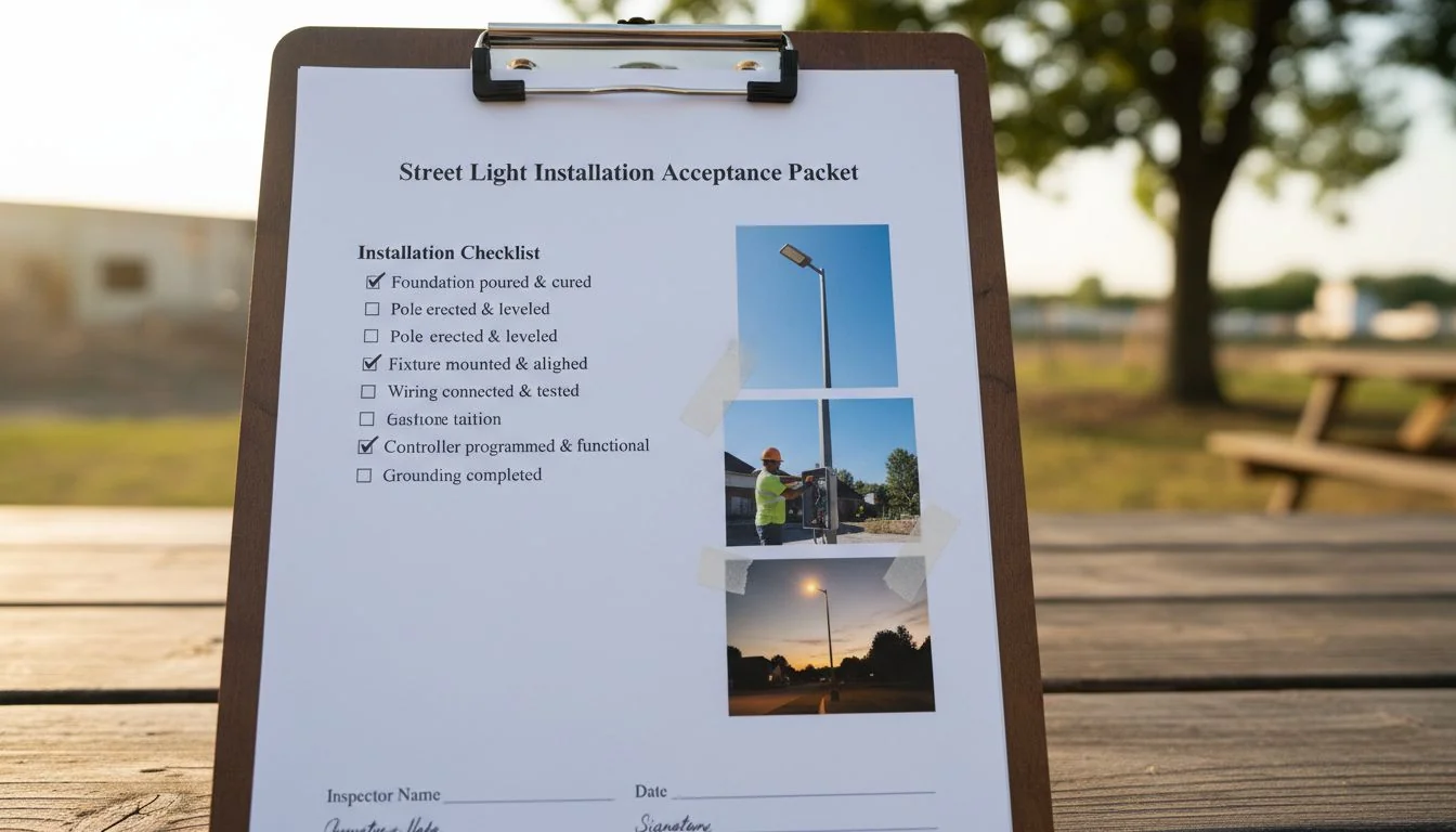
I've seen rebate applications for millions of dollars get stalled for months because of blurry photos of the thermal measurement point (TMP) or missing LM-79 reports. The utility or client isn't trying to be difficult; they need proof that what was specified is what was installed and that it's operating correctly. A standardized evidence packet is non-negotiable. It's your proof of a professional job. At Besenled, we provide this documentation support to our partners because we know it's critical for project success.
The Essential Acceptance Checklist
Build a digital folder for every single pole ID. Inside, you should have the following:
- 1. Installation Photos:
- A clear, daytime photo of the installed luminaire on the pole.
- A close-up photo of the wiring termination before the cover is closed.
- 2. Performance Verification:
- A screenshot from the lighting control system (LCS) dashboard showing the fixture is online, communicating, and reporting its energy usage.
- A photo of a digital thermometer probe on the fixture's designated Thermal Measurement Point (TMP). This proves the fixture is operating within its thermal limits, which is critical for warranty and DLC compliance.
- 3. Documentation:
- A record of the final aiming angles (Tilt, Roll, Azimuth).
- A record of the torque value used on the mounting bolts.
- A PDF copy of the specific luminaire's LM-79 (photometric performance) and TM-21 (lumen maintenance) reports.
This packet proves you did the job right, makes troubleshooting easier in the future, and sails through any rebate or approval process.
The DesignLights Consortium (DLC) requires TMP data for some premium qualifications to ensure thermal management is adequate.True
DLC Premium classification for luminaires often requires manufacturers to identify a TMP and provide in-situ thermal testing data to prove the LEDs are operating at a temperature that supports the claimed L70 lifetime.
An LM-79 report is a warranty document provided by the installer.False
An LM-79 report is a standardized photometric test report performed by an accredited lab. It details a luminaire's light output, efficacy, color, and distribution. It is provided by the manufacturer, not the installer.
Have More Questions About Street Light Installation?
You still have some specific, nagging questions. These small uncertainties can cause big mistakes on site. I'll answer the most common ones I hear from contractors to clear up any confusion.
Yes, anchor bolts need engineered torque. In a 3-pin photocell, red is load. You can aim lights with a digital level and compass. And a complete evidence packet with photos and data is what proves your install passes acceptance.
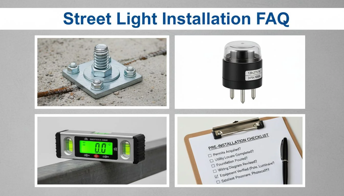
These are the questions that come up on every job. Knowing the answers separates the pros from the amateurs. Let's get these settled once and for all.
Do I need a torque value for light-pole anchor bolts?
Yes, absolutely. This is arguably the most critical structural connection in the entire assembly. The pole manufacturer or a structural engineer will specify the torque value for the anchor bolts based on AASHTO (American Association of State Highway and Transportation Officials) standards. This is not optional. Failure of an anchor bolt can lead to the entire pole falling, a catastrophic failure event. The procedure often involves a specific tightening pattern and sometimes a "turn-of-nut" method after initial snugging.
Which wire is load vs. line in a 3-pin photocell?
This is a classic question. For a standard NEMA 3-pin twist-lock photocell or receptacle, the wiring is standardized:
- Black: Line (This is the constant "hot" power coming in).
- White: Neutral (The return path for the current).
- Red: Load (This is the "switched hot" power going out to the luminaire. It is only energized when the photocell detects darkness).
Mixing up the black and red wires will result in the light staying on 24/7.
How do I aim LED street lights without a full photometric test?
You don't need a goniophotometer in the field. You just need to translate the photometric plan to reality. As we covered, the field method is simple and effective. Use a digital angle finder (inclinometer) to set the tilt and roll to the exact degrees specified in the lighting plan. Then, use a compass or a phone app to set the azimuth (rotation) correctly relative to the road. This ensures the light pattern lands exactly where the designer intended.
What proves my install passes acceptance?
Words are not enough. Data and photos are your proof. Your proof is a complete acceptance packet for each pole. This packet should contain:
- Photos of the final installation.
- Documentation of torque values and aiming angles.
- A screenshot from the control system showing the light is online and functioning.
- A photo of the TMP reading to prove thermal performance.
This evidence packet is your professional sign-off. It demonstrates you completed the job to specification and protects you from future disputes.
AASHTO provides specifications for tightening procedures for high-mast lighting tower anchor bolts.True
AASHTO's 'Standard Specifications for Structural Supports for Highway Signs, Luminaires, and Traffic Signals' includes detailed guidance on anchor bolt materials, installation, and tensioning procedures.
In a 3-pin NEMA receptacle, the black and red wires can be used interchangeably.False
The black wire is the unswitched line voltage, and the red wire is the switched load. Reversing them will bypass the photocell's switching function, causing the light to remain on continuously.
Conclusion
Mastering torque, wiring, aiming, and documentation isn't just about good work. It's about protecting your profit, your reputation, and getting paid on time. This SOP is your key.
References
-
Understanding the importance of calibrated torque wrenches can prevent costly installation errors and ensure safety. ↩
-
Learning about engineered pretension helps ensure structural integrity and prevents failures in critical connections. ↩
-
Knowing how to determine the correct torque value is critical for ensuring the safety and stability of installations. ↩
-
Understanding pull-tests can help ensure reliable wire terminations and prevent future failures. ↩
-
Understanding IP ratings helps ensure that fixtures are protected against environmental factors, prolonging their lifespan. ↩
-
A well-designed photometric plan is essential for achieving optimal lighting performance and safety. ↩
-
Using a digital angle finder ensures accurate aiming of street lights, reducing glare and improving safety. ↩
-
A complete acceptance packet is vital for project sign-off and can expedite payment and rebate processes. ↩